
Chemical Couplings
A chemically inert FEP barrier inside a flexible, watertight connection, engineered for aggressive chemical-waste drainage in labs, hospitals and processing plants.
Engineered & made in the UK · complies with ASTM C1173 & BS EN 681-1
Chemical-resistant drainage across critical facilities.
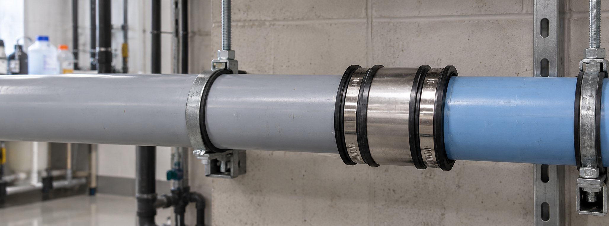
Fernco Chemical Couplings connect chemically resistant DWV pipe, fittings and waste tanks where the effluent is too aggressive for a standard coupling. One coupling transitions dissimilar chemical pipe materials and outside diameters, above or below ground.
Laboratory facilities
Chemistry, research and testing labs.
Medical & pharmaceutical
Specialized drainage in medical and pharma facilities.
Food & beverage
Beverage plants, processing and commercial kitchens.
Printing & film
Chemical-waste connections in printing and film operations.
Pulp & chemical processing
Aggressive effluent in processing plants.
Waste tanks
Connecting chemically resistant pipe to waste tanks.
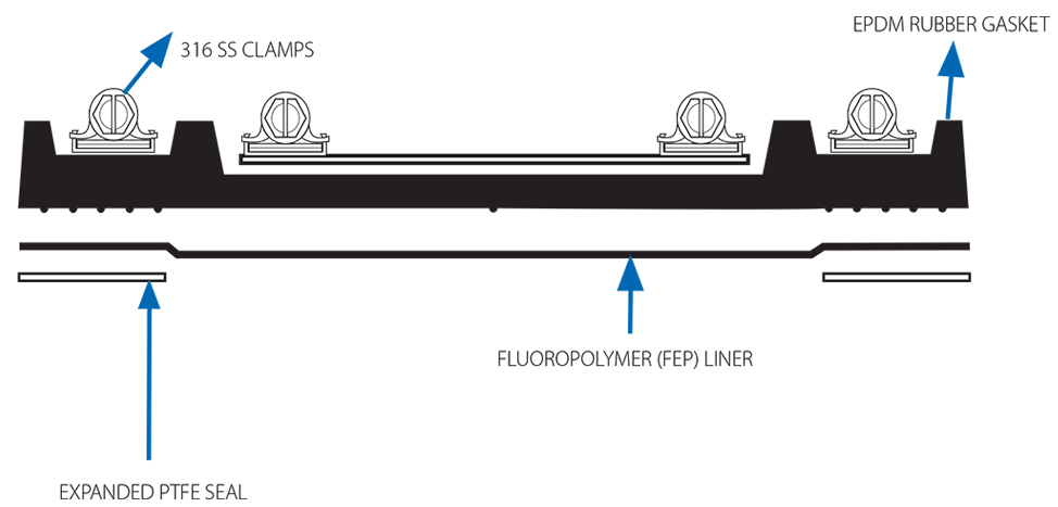
A chemical-resistant barrier inside a flexible connection.
The barrier and the mechanical connection are separate jobs, done by separate materials.
- One-piece FEP fluoropolymer liner. The primary chemical barrier, chemically inert to most chemicals.
- Expanded PTFE seals. Seal the pipe connection points beneath the liner.
- EPDM elastomeric sleeve. Provides flexibility and sealing compression.
- 316 stainless steel clamps & shear band. Reinforce the connection against shear loads.
Engineered for demanding environments.
Check chemical resistance.
Search 1013+ media for the FEP/PTFE barrier and the EPDM gasket. The FEP liner is the primary barrier, so its rating governs; the EPDM rating is shown for reference.
| Chemical medium | FEP / PTFE | EPDM |
|---|
Start typing a chemical to see its resistance rating.
Find your coupling.
Chemical Couplings are selected by the actual measured outside diameter, not nominal size. Enter each pipe's OD in inches; both pipes must fall within one coupling's range.
| Part No. | Pipe description | Min. OD | Max. OD |
|---|---|---|---|
| CC56G | 1½" PL / CI / GL | 1.73″ | 2.09″ |
| CC65G | 2" PL / CI / GL or 1½" DU | 2.13″ | 2.60″ |
| CC75G | 2" DU or 2½" PL | 2.64″ | 3.11″ |
| CC100G | 3" PL / CI / GL | 3.15″ | 3.50″ |
| CC115G | 3" DU / DI | 3.54″ | 4.29″ |
| CC125G | 4" PL / CI / GL / DU / DI | 4.33″ | 5.20″ |
| CC180G | 6" PL / CI / GL / DU / DI | 6.22″ | 7.01″ |
| CC225G | 8" PL / CI / GL / DU / DI | 8.35″ | 9.21″ |
| CC275G | 10" CI / GL | 9.25″ | 10.59″ |
| CC290G | 10" PL / DU / DI | 10.63″ | 12.09″ |
| CC335G | 12" PL / CI / GL | 12.25″ | 12.75″ |
| CC345G | 12" DU / DI | 12.75″ | 13.50″ |
Bushes accommodate larger OD differences between the two pipes. Custom sizes available on request.
A heat-shrunk FEP barrier, in five steps.
The FEP liner is shrunk onto the pipe with hot air, so the barrier is continuous through the joint. Follow the instructions supplied with the coupling.
Prep the pipe
Chamfer and deburr both pipe ends and confirm they are clean.
Mark and tape
Mark the seal positions and apply PTFE tape directly over the marks.
Set the PTFE seals
Fit the expanded PTFE seals so they sit directly beneath the clamp bands.
Shrink the FEP liner
Slide the FEP liner over the seals and apply even hot air to shrink it onto the pipe.
Tighten and test
Center the coupling over the liner, tighten the bands to the rated torque and leak test.
See the connection process.
Literature.
Resistance chart, data sheet and catalog for Chemical Couplings.
Chemical Coupling FAQs.
Materials, sizing, applications, compliance and performance.
What pipe materials do Chemical Couplings connect?
They accommodate plastic, cast iron, glass, Duriron and ductile iron pipe. Always select the coupling by the actual outside diameter of each pipe, not the nominal size.
Can they transition different pipe materials and sizes?
Yes. Chemical Couplings transition between compatible chemical pipe materials and outside diameters, as long as both pipe ODs fall within the selected coupling's published range.
How do I know a coupling resists my chemical?
Use the resistance lookup on this page or the full resistance chart. Ratings are for the FEP/PTFE barrier and the EPDM gasket. Resistance is tested at 70°F; higher temperatures, higher concentrations and longer exposure can reduce it, so confirm the specific medium and conditions before installing.
What is the barrier made of?
A one-piece FEP (fluoropolymer) liner and expanded PTFE seals form the chemical barrier. FEP and PTFE are chemically inert to most chemicals, with exceptions such as molten alkali metals, fluorine at elevated temperatures and complex halogenated compounds. An EPDM sleeve provides sealing compression and 316 stainless steel clamps and a shear band reinforce the connection.
Can they be installed below ground?
Yes, they are suitable for both above- and below-ground chemical-resistant drainage. Always review installation requirements and local codes for the specific project.
What are the temperature and pressure limits?
Minimum -50°F; maximum 212°F under consistent exposure and 266°F intermittent. Maximum test pressure is 4.3 PSI. Chemical Couplings are for chemical-resistant drainage and DWV, not pressurized process piping.
What standards do they meet, and where are they made?
Chemical Couplings are engineered and made in the UK by Fernco, a BSI-certified manufacturer (ISO 9001), and comply with ASTM C1173 and BS EN 681-1. Because they are not made in the USA, they are not AIS or BABA compliant.
How are they installed?
Chamfer and deburr the pipe ends, apply PTFE tape and the expanded PTFE seals beneath the clamp bands, slide the FEP liner over the seals and shrink it to the pipe with a heat gun, then center the coupling and tighten the bands to the rated torque and leak test.